Extract it. In there , there is a folder called adafruit_hid , copy that folder to the pico where circuit python is already installed.
remember to transfer the python file with name “code.py” to pico, to run on boot.
This is the example for Mouse:
import time
import board
from digitalio import DigitalInOut, Direction, Pull
import time
import usb_hid
from adafruit_hid.mouse import Mouse

mouse = Mouse(usb_hid.devices)


x=0
y=0
mouse.move(x,y)
# This will move the mouse from it's current position to x pixels
# and y pixels.
# So if the current position is (100,200) it'll move to
# (100+x,100+y)
This can also be used with a button so that it keeps the screen of pc awake ,like this:
import time
import board
from digitalio import DigitalInOut, Direction, Pull
import time
import usb_hid
from adafruit_hid.mouse import Mouse

mouse = Mouse(usb_hid.devices)
btn = DigitalInOut(board.GP14)
btn.direction = Direction.INPUT
btn.pull = Pull.DOWN
i=0
on=False
def onRelease():

    bState=btn.value
    released=False
    if (bState):
        bState = btn.value
        while bState:
            bState = btn.value

        return True;


while True:

    if onRelease():
        on=not on
    if on:
        mouse.move(5,5)
        time.sleep(0.1)
        mouse.move(-5,-5)
        time.sleep(0.1)
    time.sleep(0.1)
This is the example for Keyboard.
import time
import usb_hid
from adafruit_hid.keyboard import Keyboard
from adafruit_hid.keycode import Keycode

key_A=Keycode.A
key_Shift = Keycode.SHIFT
keyboard=Keyboard(usb_hid.devices)

time.sleep(2)
keyboard.press(key_Shift, key_A)
keyboard.release(key_Shift, key_A)
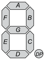
Most Digital clocks are made up of 4 7-segment display. A seven segment display is 7 leds arranged in specific manner that when some light up it forms a number ranging from 0-9 or letters from A-F.
What the machincal clock does is used servo motors as an led. so when you see the carboard cutout from top it replicates led_on and when looked from side looks like led_off.
Parts Needed
I used :
Arduino Uno
!6 bit channel Servo Controller.
Carboard Cut hexagon shapes.
Math behind the Cardboard Cutouts.
I initially thought that cutting the hexagon cutouts was easy. In fact it was quite challenging. I had to find a perfect ratio.
cut a rectangle with ratio 1:3 . I used 3:9 cm.
draw a horizontal line across of length(1/2 of the short side ) from top and bottom of the long side. (Line T and B)
Draw a verticle line from shor side to the other in the middle. ( center U and D)
Connect U with edges Of T and D with B. then cutout thoses triangles to form a hexagon.
The diagram of one Hexagon. Recommended size is 3:9 cm but as long as the ratio is 1:3 the hexagons will fit perfectly
A while ago I did my first certification in Python through soloLearn.. I wrote about here and said that I look forward to doing the PCEP certification, and surprise surprise I actually did it.. I’m really proud of it.
I did this in a app called SoloLearn. Although I pretty much new most of the things in the course, I did not have any solid proof, well now I have one. I am looking forward to get PCEP aka PCEP – Certified Entry-Level Python Programmer.
I had this idea of making a digital Dice in arduino, which would be rolled when you wave a hand over it. It took me a lot of time so I won’t share the code or schematics, but here is the video.
I’ve always wanted to make a Robot dog or a spider ( I did make the spider eventually) but one day I wanted to make a robot dog, I only had 4 servos at that time and it was practicaly impossible to make a robot dog out of it, because we need 8 servos for balance and 4 servos for turning (12DOF) , I think it can also be done in 4 for balance and 4 for turning, but I never tried, back to the story, I was determined to take up a challenge and I started thinking negatively, that it was impossible, but eventually I reached somewhere.
At first i though this is not a dog, but it turned out I had made a Frog, I dicided to name it MiMo. It can only walk forward because I didn’t add any servos for turning due to a major problem.
the servos I used were made for carrying light Objects and not for robots, the arduino uno was very light and it worked perfectly with an external supply. But when I attached a battery (9v was necessary), MiMo would not be able to even move, so I dumped the Arduino Uno(size of a credit card) and used an Arduino nano( size of a pendrive), but it still was too heavy, I tried changing the batteries to smaller ones but it did not work. The only option was to get a LiPo battery but the small size, light-weight and 9v was too costly, so I gave on the idea and salvages the parts for other usefull projects.
N-A-R stands for Not A Robot, but it is a robot, that I made. It is an 8-DOF robot, i.e. 8 degrees of freedom, so it can move in 8 different ways. Image DOFs as joints in our body. When we move our elbow, we are using one of many DOF in our body, similarly the robot uses Servos for joints and as i have used 8 servos, N-A-R has 8DOF.I also made a post about X-O-R, which is a 17 DOF robot, which of course can move in 17 different ways, both of them were challenging, because X-O-R was big and heavy but was easy to make it walk due to it’s 17 DOF, but N-A-R was harder, even though it was smaller, I had very limited option/ degress of freedoms, it was certainly easier to balance than X-O-R but this took a lot of thinking.
If i went to explain everything we would be here all day, so that is a post for another time, until then GoodBye 🙂 .
Using sound to calculate short distance in a pretty good way of measuring distance, though it may not be a 100% accurate and cannot be fully depended on, it is a fun project to make and understand Sound.
The HC-SR04 ultrasonic sensor is most commonly used in projects. Ulrasonic sensors have 2 speakers, trigger (trig) and echo, the trig produces sound, and echo listens to it, the sound in on an ultrasonic level aka Ultrasound which cannot be heard to the human ear, the frequency of ultrasound is about 2-200 MHz (mega heartz) whereas a human can hear only 2000-5000 Hz.
The sensor can be controlled/ used with a micro-controller. when the ‘trig’ speaker is turned on it produces a sound wave, when the wave hits an object it is reflected, when the sound his the ‘echo’ speaker, the duration the wave took to travel from ‘trig’ to ‘echo’ is send to the micro-controller, in our case an Arduino Uno. The duration( in microseconds) can be converted to inches or centimetres. The following image explains everything.
Connecting and using with Arduino.
The circuit diagram for the connections is given below, it can be used with almost all mainstream Arduinos.
#define echoPin 2 // attach pin D2 Arduino to pin Echo of HC-SR04
#define trigPin 3 //attach pin D3 Arduino to pin Trig of HC-SR04

// defines variables
long duration; // variable for the duration of sound wave travel
int distance; // variable for the distance measurement

void setup() {
  pinMode(trigPin, OUTPUT); // Sets the trigPin as an OUTPUT
  pinMode(echoPin, INPUT); // Sets the echoPin as an INPUT
  Serial.begin(9600); // // Serial Communication is starting with 9600 of baudrate speed
  Serial.println("Ultrasonic Sensor HC-SR04 Test"); // print some text in Serial Monitor
  Serial.println("with Arduino UNO R3");
}
void loop() {
  // Clears the trigPin condition
  digitalWrite(trigPin, LOW);
  delayMicroseconds(2);
  // Sets the trigPin HIGH (ACTIVE) for 10 microseconds
  digitalWrite(trigPin, HIGH);
  delayMicroseconds(10);
  digitalWrite(trigPin, LOW);
  // Reads the echoPin, returns the sound wave travel time in microseconds
  duration = pulseIn(echoPin, HIGH);
  // Calculating the distance
  distance = duration * 0.034 / 2; // Speed of sound wave divided by 2 (go and back)
  // Displays the distance on the Serial Monitor
  Serial.print("Distance: ");
  Serial.print(distance);
  Serial.println(" cm");
}
The code above can be uploaded to an Arduino can can be used easily.
So today I made my first Android App And I am soon going to publish it. It is a rubik’s cube companion. It is easy-to-use, and fairly simple. It has many options like a StopWatch, Timer (to Set a goal and beat your PB) . It also has a tutorial. It is not that great but good for beginners. The main Feature is Compatiblity with Arduino. You can use an UltraSonic Sensor And HC-06 or HC-05 with Arduino. Here are the schematics.
So the ultrasonic can be used as a Trigger for the timer on the app. Here is the code…
const int trigPin = 7; // Trigger Pin of Ultrasonic Sensor
const int echoPin = 6;
long dis;
int state=0;
long getCm(){long duration, inches, cm;
   pinMode(pingPin, OUTPUT);
   digitalWrite(pingPin, LOW);
   delayMicroseconds(2);
   digitalWrite(pingPin, HIGH);
   delayMicroseconds(10);
   digitalWrite(pingPin, LOW);
   pinMode(echoPin, INPUT);
   duration = pulseIn(echoPin, HIGH);
   cm = (duration/29)/2;
   delay(100);
   return cm;}
void setup() {
  // put your setup code here, to run once:
Serial.begin(9600);
}

void loop() {
//Serial.println(getCm());
dis = getCm();
//Serial.println(dis);
if(dis<=17 && state ==0){ // You Might want to change the 17 (dis) to more or less depending on your
                           // needs.
dis = getCm();
  do{
 dis = getCm();
 if(dis>17){
  state = 1;
  Serial.println(state);
  break;
  }
    }while(dis<=17);

}
else if(dis<=17 && state ==1){
    state = 0;
    Serial.println(state);
    dis = getCm();
    while(dis<=17){dis = getCm();}
  }
}
On the Phone click Dev-StopWatch or Arduino button. And then press Connect, Choose your bluetooth module connected to Arduino and Enjoy 🙂 ….